In 1965, the Victor Mk 2 was fitted with a side-scan radar capability and a Rapid Processing Unit (RPU) display. When in use, the H2S scanner was locked at 90 degrees to aircraft track, and the radar video diverted from the normal scanning timebase on the Plan Position Indicator (PPI) display to a six-inch wide, low afterglow CRT in the RPU. Photographic paper was drawn across this CRT at a speed proportional to the groundspeed of the aircraft appropriate to the range scale selected. The exposed image was developed as the paper passed over two slots in the top of the unit through which developing and fixing chemicals were sucked. Although it sounds hazardous to employ hot and corrosive chemicals in a pressurised aircraft cabin, the system was very successful in that the radar image produced was much sharper and with a much wider spectral range than the normal high afterglow PPI. It also produced a permanent image which allowed the Nav Radar time to study the returns more carefully before making any updates.
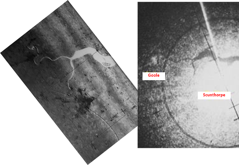
Figure 1. A comparison of the RPU and PPI displays of the Humber.
The front platen of the RPU faced backwards beside the NBS Calc 3 behind the Nav Radar’s seat. To use it, the Nav Radar selected either port or starboard scan and used his swivel-seat to turn round and face forwards. In a similar manner to the way the Fix controls on the NBS, or the GPI Mk 6, produced range and bearing markers on the PPI at the predicted position of the selected latitude and longitude, so markers were produced on the RPU display but with a difference. As the scanner was fixed sideways at 90 degrees to track, the bearing marker always appeared as a line strobe in that direction as the aircraft passed the predicted fixpoint. The range marker was not a circle but a hyperbola which appeared at the edge of the paper display and swung across to intersect the bearing marker at the closest point of approach to the predicted fixpoint before sweeping back to the display edge; these markers can be seen on left hand image of Figure 1 and in the later figures below. To make a fix update, the Nav Radar used two wheels to move a small black cross on a plastic ruler onto the displayed intersection of the markers; he then selected Fix on the RPU and moved the cross over the radar image of the fixpoint and either he accepted this update on the NBS, or the Nav Plotter accepted it on the GPI Mk 6, whichever system was being updated. One quirk I remember was that the ruler was moved by small and rather delicate chains controlled by the two along and across control wheels. These chains inevitably had some slack, so the technique we used was to move the cross onto the marker intersection in the same direction as we needed to move it onto the radar image, thus ensuring the update didn’t contain any slack from the chains.
The performance of the floated gyros used in the Blue Steel inertial navigation system (INS) was not stable enough to maintain a good accuracy for much longer than the expected flight time of the missile, originally six minutes for a high level launch. So once airborne, the INS was aligned in the climb and selected to a mode where Green Satin Doppler velocities (N/S & E/W) were compared with the IN velocity outputs, and the differences used to torque the INS stable platform and its levelling gyros. The first assumption was that the Doppler velocities were correct, and that if the IN velocities were the same then the platform must be at right-angles to the local earth gravity vector. The INS was initially aligned in azimuth using the aircraft’s gyro-magnetic compass corrected for local variation, and then continually corrected throughout the sortie using a Fix Monitored Azimuth (FMA) technique. This involved the Nav Radar using the H2S radar (either with the PPI or the RPU) to fix the GPI Mk 6 as accurately as possible and letting it run using IN heading for 150-200 nm (about 20 minutes flight time) in a reasonably straight line, when he fixed again. The second assumption was that any across track error was caused by IN azimuth gyro error, and this was torqued out automatically by accepting the fix on the GPI Mk 6 with other settings made that represented the track and distance between the fixes. The GPI Mk 6 was the key element in the integrated navigation system having been designed specifically to act as the interface between the aircraft navigation system and the missile.
Some Nav Radar’s at Wittering were not comfortable with the RPU and continued to use the PPI for fixing the GPI Mk 6 and updating the Blue Steel inertial navigation system (INS). However, I really enjoyed using it and did so when my 100 Squadron crew launched Missile No. 175 in Aberporth Bay as part of Operation Fresno. The examples of the RPU display shown below, together with a current Google Earth image, are taken from that sortie and illustrate the clarity of the RPU radar image. Operation Fresno was intended to show that the Blue Steel system was successful in squadron use flown by operational crews and maintained by RAF technicians, rather than R&D trials crews and company personnel. Known as Post Acceptance Launches, our firing on 27 May 1966 was the first of four. A 139 Squadron crew launched the second on 26 August 1966, and a further two were launched by Vulcan crews from Scampton on 31 May 1967 and 7 July 1967.
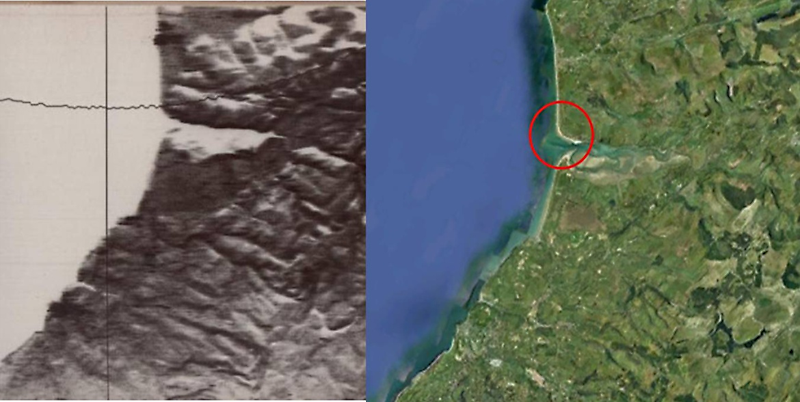
Figure 2. The Dovey Estuary.
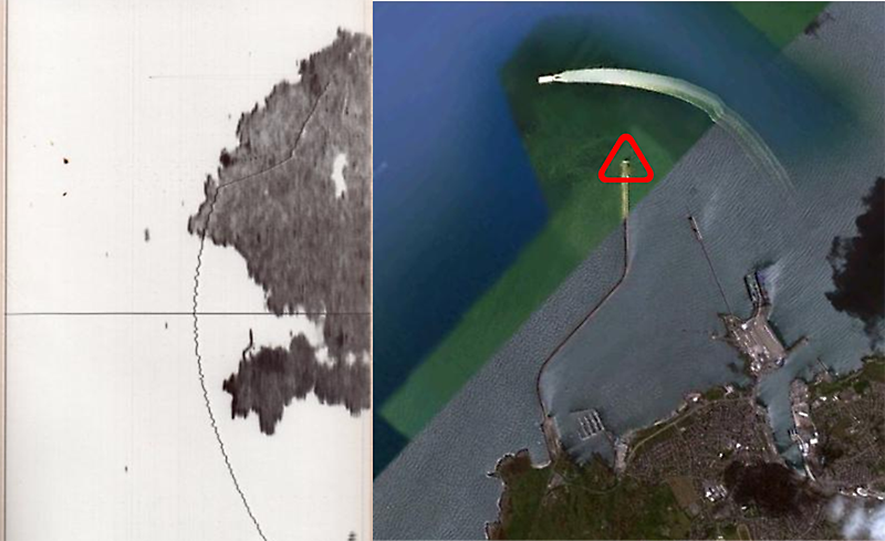
Figure 3. Holyhead Pier with an enlarged Google Earth image (including a High Speed Ferry.)
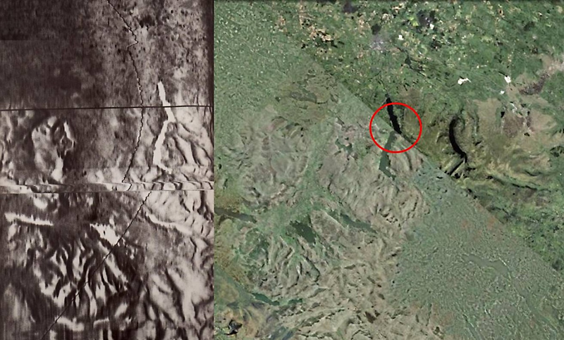
Figure 4. Ullswater.
The RPU was only fitted to the Victor Mk 2; I believe this small scale introduction was really aimed at developing the technique for the ill-fated TSR2 in which an RPU based side-scan radar was the primary fixing aid.
Air Commodore Norman Bonnor
President 100 Squadron Association